news
Discover our Battery Emulator solution
Our Battery Emulator is combined with a regenerative converter designed to behave like real batteries
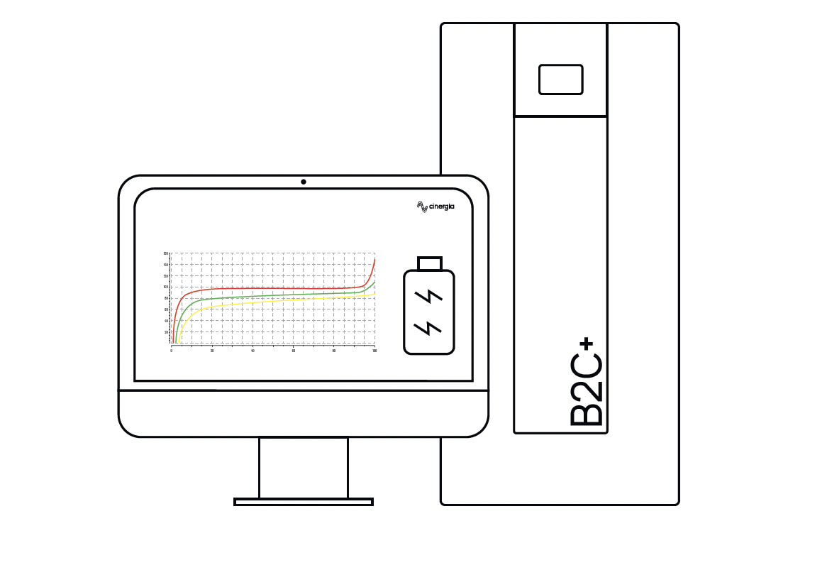
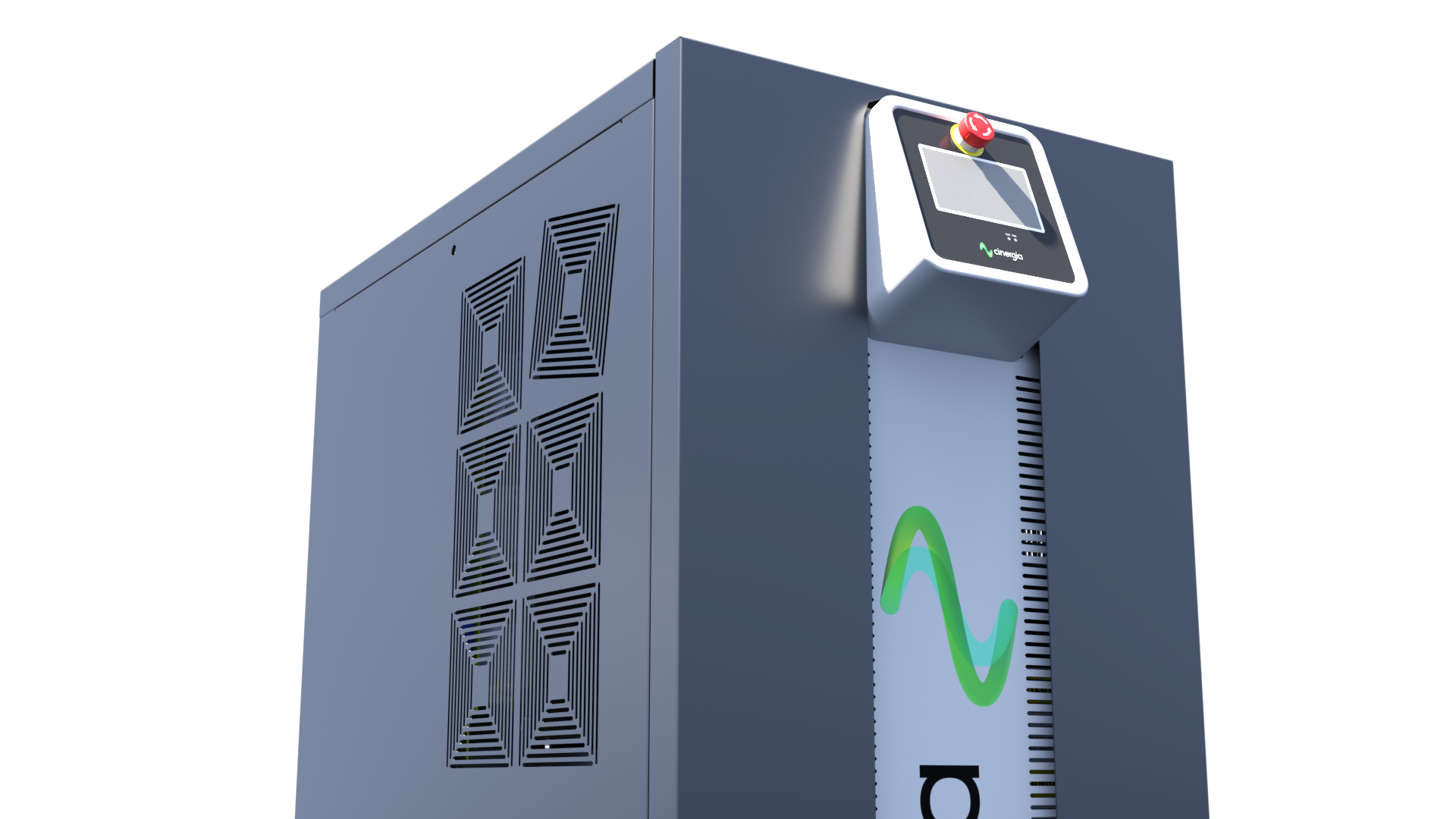
Cinergia's Battery Emulator is combined with a regenerative AC-to-DC converter designed to behave like real batteries. It is a software option of the B2C+ with a DC output, for a single unit, from 20 to 750V (800V with the HV option).
It is also possible to serialize units to reach up to 1500V or to parallelize units to increase the power and current. Thanks to the separated channel operation (included up to 54kW) each unit can be used as 3 completely different DC Regenerative Power Supplies in a single cabinet.
Our Battery Emulator is the software option of the B2C+ with a DC output. A versatile and flexible product line perfectly suitable for Battery Testing and Characterization procedures.
Clear and intuitive battery emulator
CINERGIA offers a solution that is characterized by a clear and intuitive design. Its easy handling saves us time in the test setup.
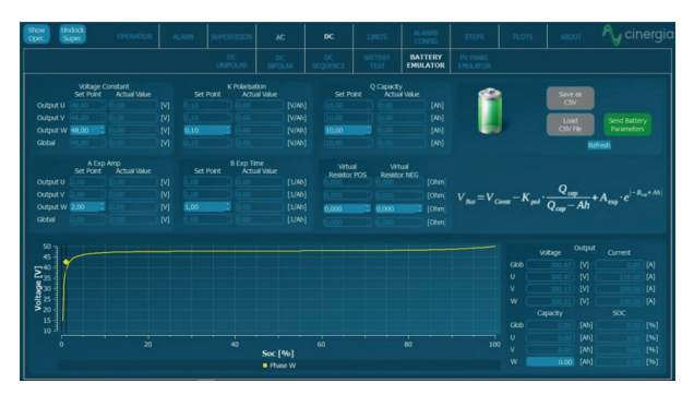
Control Buttons
Save as CSV - Save all parameters of the configuration in a CSV file, to use anytime.
Load as CSV - Load parameters of configuration from the CSV file.
Send Battery Parameters - It is always necessary to send the parameters. If the user uploads a csv file and does not click on this send button, the parameters will not be introduced to the converter. To find out if the parameters are correctly entered, compare in A if the setpoint values and the actual values are the same.
Battery Parameters
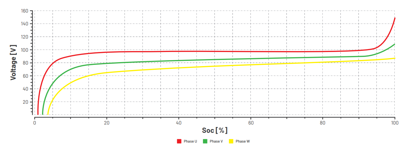
Voltage Constant - This voltage is usually indicated by the battery manufacturer. It is where the two exponentials meet on the graph, so it is approximately the voltage at the center of the graph.
A Exp Amp - It is the voltage that will be increased from the Voltage Constant depending on the battery technology. If the Ah (explained later in the Output Parameters part) is 0, which means that the battery is fully charged, the maximum voltage will be Voltage Constant + A Exp Amp. This parameter describes the slope on the right side of the graph (the one that makes the voltage go to the maximum).
K Polarisation - This parameter describes the left slope (the one that makes the voltage go to 0).
B Exp Time - Describes the duration of the horizontal part of the line on the graph.
Q Capacity - Capacity of the battery in Ah.
Virtual Resistance - This resistance is also delivered by the battery manufacturer, and is the parameter that sets the voltage drop depending on the current flowing through each channel. So, for example, if the voltage is 100V, the resistance is 1Ω and the current is 10A, the voltage drop will be of 10V, so the voltage at the output will be 90V instead of 100V. When the current is positive, the virtual resistance that will affect is the positive one, while if the current is negative, the virtual resistance will be the negative one.
Graph Voltage-SOC
The graph Voltage-SOC represents in real time the state of the battery for each channel. There is a point represented in each line that shows the exact point of the charge.
Mathematical Model
The channel/s configured in battery emulator mode will work as a Constant Voltage source where the voltage is a function of a battery model, as described by the equation below:
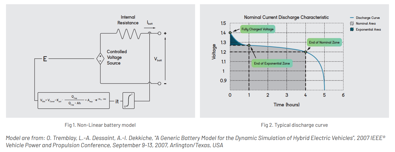
The mathematical model is saved and executed in the DSP firmware, so it warrants precise and deterministic behaviour, but the model cannot be changed. The user can emulate different batteries by adjusting the model parameters and the battery parameters (cells in series/parallel, capacity of the cell, etc.).
Output Parameters
The output parameters show the values in the output of the converter such as voltage and current. The SOC [%] represents the real time state of charge.
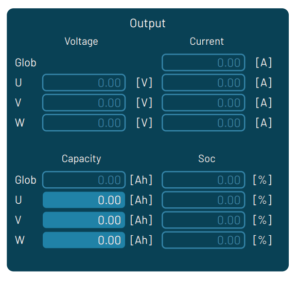
In this part there is also the Capacity [Ah] which can be modified online while the converter is in Run state. It will be useful to make a battery go to any part of the line and do not have to wait until it reaches the desired part. So, for example, if the capacity (Q Capacity) of the battery (introduced in part A5) is 10Ah and the user sets a Capacity of 5Ah in the E part, the SOC of the battery will go to 50%.
ANY QUESTIONS? TALK TO OUR ENGINEERS
Related content:
Sie können den gesamten Fall hier herunterladen
HERUNTERLADENWeitere Artikel
news
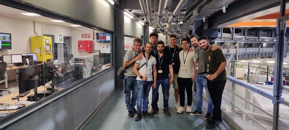
Exploring Innovation at ALBA Synchrotron
The visit was incredibly insightful and inspiring, providing us with a deeper understanding of the cutting-edge research and technology that drives their work.
news
Powering the Future: Cinergia at Mobile World Congress 2025
The future of connectivity demands reliable and sustainable power. At Mobile World Congress 2025, Cinergia will showcase how our cutting-edge power solutions are meeting this challenge head-on.

news
Do you need to emulate electrical loads?
Our EL+ vAC AC is a current source designed to emulate the electrical behavior of passive and active devices connected to the grid
news
We have updated our datasheets
The new datasheets enhance the previous ones by providing a more detailed description
