case-study
Motorsport battery testing with a CINERGIA's B2C+ bidirectional converter
Discover the accelerated life testing protocol used to determine if the cells can withstand a whole season with this workload

Introduction
Regenerative braking is an important technology in electric motorsport, as it allows batteries to be smaller and, therefore, lighter. In the Formula Student Electric racing category, where ETSEIB (Barcelona School of Industrial Engineering) Motorsport participates, the amount of recovered energy can be particularly high because the engines may be mounted on all four wheels of the vehicle. For the battery, regenerating by braking means short bursts of high current that accelerate cell wear.
This article presents the accelerated life testing protocol that ETSEIB Motorsport has used to determine if the cells can withstand a whole season with this workload.

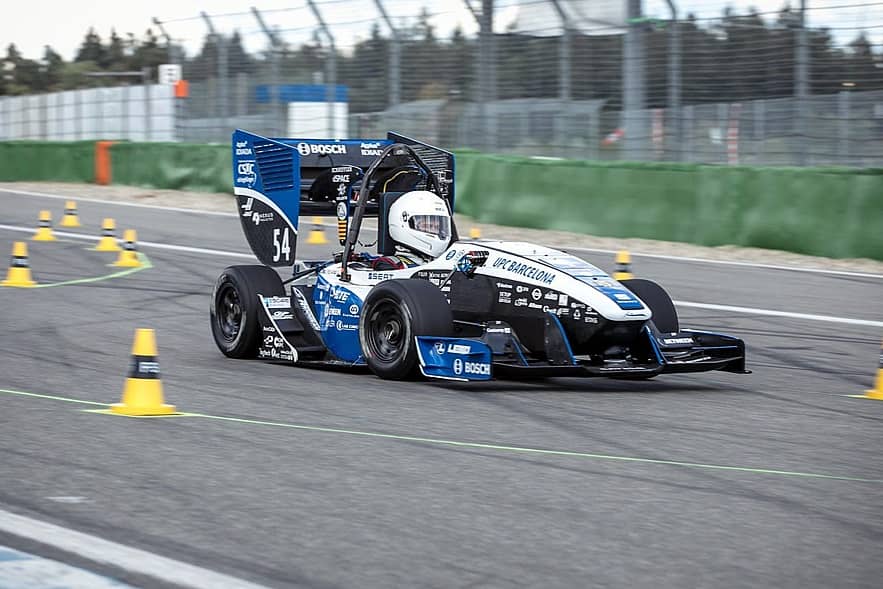
The CAT12e, ETSEIB Motorsport's car for the 2018-2019 season
Features of the B2C+ 30 bidirectional converter
3 channels.
± 30A per channel (90A when working in parallel mode).
20 to 750V in unipolar connection, -350 to 350V in bipolar connection.
30kVA.
Operating modes: constant current, constant voltage, constant power, constant impedance and CC-CV-CC-CV battery charging.
Controllable through its touch screen or by connecting a computer (comes with a user-friendly interface).
Returns the discharged current to the grid.
In this application, the unipolar parallel mode has been used as currents of 75A are needed. The user interface has been essential as it allows you to send a current profile by opening a csv file.
Testing rig

Platform details:
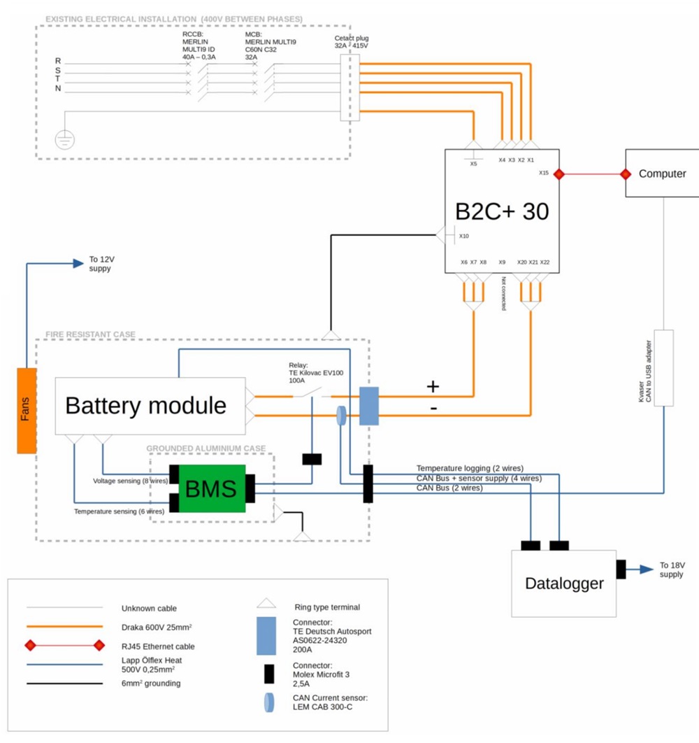
AC/DC Converter: Cinergia B2C+ 30.
Battery module: Melasta li-ion pouch cells. 7s1p configuration. For each cell: 3V to 4.2V and 6.8Ah.
BMS: self-developed. Opens the power circuit if cell voltage or temperature values go beyond safe levels.
Datalogger: self-developed. Saves current and temperature readings every 20 ms.
Current sensing: LEM CAB 300-C (hall effect).
Temperature sensing:3Vishaylugtypethermistors.
Fire-resistant battery container on a handcart, for safety reasons.
Methodology
The experiment involves discharging the module 50 times by repeatedly applying a current profile that simulates one lap of a race. The profile has been obtained from the modification of real data that was recorded during the previous season.

The used current profile
It should be noted that for high SoC values, another profile that doesn’t have positive (charging) currents has been used to avoid reaching voltages that are too high for the cells.
Each of the 50 cycles has the following structure (we chose a fully charged module as the start and end point of the cycle):
Turn on the datalogger.
Apply the current profile repeatedly until a cell reaches 3.2V.
Turn off the datalogger and turn on the fans.
Let the cells rest for 10 minutes or until they reach 45ºC (datasheet value for continuous charging).
Charge the module at 5A.
During charging, keep the fans on until the module reaches room temperature.
The charging cut-off voltage is 4.19V.
Let the cells rest for 10 minutes.
Calculate capacity by coulomb counting and make sure its value is not too low before beginning the next cycle.
Each one of these cycles takes approximately 2 hours.
In order to be in a worst-case scenario, the module has been thermally insulated, so it approaches its maximum operating temperature (60ºC) at the end of the discharge.
Safety considerations
Repeatedly applying high currents to lithium cells always has a risk. The testing rig has been designed so that, in case of a battery fire, the fire could not spread nor hurt anybody. This has been achieved by using a fire-resistant battery container, which is itself mounted on a handcart. The handcart combined with easy-to-disconnect wiring makes it possible to push the module to a concrete courtyard within 30 seconds of the detection of the problem.
Results
Apart from visually inspecting the cells, the indicators that have been used to assess the cell’s state of health are capacity fade and internal resistance rise.
Capacity fade:

Capacity [Ah] evolution through the 50 discharges
The average of the first 5 values is 6.30 Ah and the average of the last 5 is 6.17 Ah. This represents a relative decrease of 2%.
Internal resistance rise:
What has been measured is the difference between the maximum temperature reached by the module and the ambient temperature. This indicator has been considered sufficient to detect significant changes in internal resistance.

Temperature rise above ambient [oC]. Evolution through the 50 discharges
The average of the first 5 values is 33.92 ºC and the average of the last 5 is 34.76 ºC. This change has not been considered significant.
Conclusions
None of the measurements show any worrying signs of ageing whatsoever. The fact that seven cells have been tested at the same time gives proper significance to the results, providing confidence that this workload can be applied to the whole battery pack.
Author: Pol Molénat Gené
Powertrain Department, ETSEIB Motorsport.
You can download the whole case here
Download


